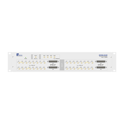
BSWM-4X32CSR
BSWM-4X32CSR is a universal, blocking RF switch matrix for bi-directional multi signal routings. Common applications for this product are product validation tests for DUTs (Device Under Test) with multiple antenna ports, known from automotive or MIMO modules. The device offers 4 ports for measurement instruments. All 4 non-reflective instrument ports can be routed to 32 DUT ports. In the case of non-routing, the ports are matched to 50 ohms of impedance. For each available DUT port there is also a corresponding DC functionality to allow simulating a load or injecting phantom DC supply.
Due to its high bandwidth from the BSWM-4X32CSR is capable to route signals of almost all current broadcast and communication standards like AM, FM, DAB3 like GSM900, GSM1800, UMTS, LTE 4G, LTE 5G FR1, IEEE 802.11a/b/g/n/ac/ax (Wi-Fi 6E) and 802.11be (Wi-Fi 7).
100 kHz ... 8000 MHz DC load simulation 4X32 ports
Parallel Testing
Due to its good isolation properties, the matrix allows time efficient testing of versatile signals in level and frequency on multiple channels at the same time without influence to each other.
Extensive DC tests possibilities
The BSWM-4X32CSR offers versatile test and simulation functions for DC tests of the DUTs. Each of the 32 channels are equipped with wear free, solid state DC power switches. This allows the insertion of stimulation voltages (14V/18V) and tones (22 kHz) to control the DUT switching state and also the simulation of LNB (Low Noise Blocks) loads. With internal switches a DC short (coaxial cable is shorted) or open state (coaxial cable is broken) can be simulated. An overload protection circuit prevents damage to the module from excessive current loads.
Internal Volt and Ampere Meters
Via the integrated volt and ampere meters, the (14V/18V) control voltage and the current flow can be measured simultaneously in all 32 channels. The volt and ampere meters have high impedance inputs and thereby are negligible in influence on the current flow in the BIAS-Ts. The current measurement range is ± 500 mA. By application of the 14V/18V control voltage the current flows into the DUT via the BSWM-4X32CSR. In the case LNB simulation the current flow comes out of the matrix.
If the current exceeds the maximum value of ±500 mA, the SHORT, LOAD A and LOAD B switch will be opened automatically. After a RESET by software the SHORT and LOAD switches will be closed again.
Wear free RF switching
Modern fast responding solid state RF switches with high RF power capability are used in the BSWM-4X32CSR matrix. This allows reproducible tests with a huge number of switching cycles and fast switching times of few microseconds.
Remote control with Trigger
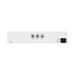
For remote control the BSWM-4X32CSR matrix offers a LAN interface and a trigger input. The matrix can be controlled via simple ASCII strings. A “queue” function allows preloading switching configurations to the matrix device and a triggered execution by trigger pulses. After a positive TTL trigger slope to the trigger input, the preloaded switch configuration will be executed only by hardware in micro seconds. While the trigger receiver is processing, the trigger signal is forced to LOW for a typical 10 ms and all subsequent trigger signals are ignored until the trigger receiver is ready again.
Variable mountable
The BSWM-4X32CSR is housed in a 19”, 2 U cover with variably mountable brackets for mounting in 19” racks. The brackets can be mounted on the front or the rear side of the device. This allows the BSWM-4X32CSR to be mounted front or back in 19" racks. The brackets can be mounted in ½ 19-inch grids over a range of approximately 15 cm, allowing the BSWM-4X32CSR enclosure to be moved in place. All RF ports and the trigger input are located on the front panel to enable RF connections via short RF cables to the measurement equipment.
letzte Änderung: 27.08.2025


